Pipeline Thermal Insulation

Oilfield pipelines are insulated mainly to conserve heat. The need to keep the product in the pipeline at a temperature higher than the ambient could exist for the following reasons including:

  • Preventing formation of gas hydrates
  • Preventing formation of wax or asphaltenes
  • Enhancing product flow properties
  • Increasing cool-down time after shutting down
  • Meeting other operational/process equipment requirements

In liquefied gas pipelines, such as LNG, insulation is required to maintain the cold temperature of the gas to keep it in a liquid state. This chapter describes commonly used insulation materials, insulation finish on pipes, and general requirements for insulation of offshore and deepwater pipeline.


Source :
Guo, Bouyun. Offshore Pipeline

Pipeline On Bottom Stability

On bottom stability analysis is performed to ensure the stability of the pipeline when exposed to wave and current forces and other internal or external loads (e.g. buckling loads in curved pipe sections). The requirement to the pipeline is that no lateral movements at all are accepted, or alternatively that certain limited movements that do not cause interference with adjacent objects or over stressing of the pipe are allowed.

Hydrodynamic stability is generally obtained by increasing the submerged weight of the pipe by concrete coating. There are other ways such as increasing the steel wall thickness, placing concrete blankets or bitumen mattresses across the pipeline, anchoring or covering it with gravel or rock. Alternatively, the hydrodynamic forces may be reduced by placing the pipeline in a trench on the seabed, prior or subsequent to installation. The natural backfilling of a pipeline depends on the environmental conditions and the seabed sediment at the location.

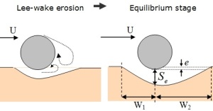
A pipeline on the seabed forms a structural unit where displacement in one area is resisted by bending and tensile stresses. The real situation most probably involves a great variety of pipeline-seabed interface conditions. pipeline self lowering may result in some sections of a pipeline being embedded to a larger degree than determined by touchdown forces, and parts may even be fully buried. The embedment is influenced by soil characteristics and phenomena such as scour, sediment transport and other seabed instabilities. In other sections the pipe may be slightly elevated above the seabed due to seabed undulations or scour processes. For both conditions, the hydrodynamic forces are reduced relative to the idealized on bottom condition.

Source:

Click to access mohdridzaba030064d07ttt.pdf

Pipeline Free Span Mitigation

Surface laid pipelines can experience free-spans due to various reasons; uneven seabed and local scour. If free-spans are long, the vortex induced vibrations (VIV) can cause the pipeline to undergo fatigue damage and severely reduce the pipeline design life.

118-15

Free-spans can be rectified by,

• Pipeline Lowering (PL) Method

• Grout/Sand bag placement

• Rock dump placement

The selected method for rectification depend on the pipeline details, location, water depths and cost details.

Source:

http://www.capegroup.net/products-services-46/total-oilfield-pipeline-solutions-50/free-span-assessment-rectification-118

Pipeline Hot Tap

Hot tapping is an alternative technique that allows the connection to be made without shutting down the system and venting gas to the atmosphere. Hot tapping is also referred to as line tapping, pressure tapping, pressure cutting, and side cutting. The process involves attaching branch connections and cutting holes into the operating pipeline without interruption of gas flow, and with no release or loss of product. Hot taps permit new tie-ins to existing systems, the insertion of devices into the flow stream, permanent or temporary bypasses, and is the preparatory stage for line plugging with inflatable, temporary balloon plugs (stoppels).

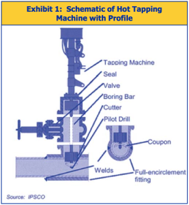
Hot tapping equipment is available for almost any pipeline size, pipe material, and pressure rating found in transmission and distribution systems. The primary equipment for a typical hot tap application includes a drilling machine, a branch fitting, and a valve. Hot tapping equipment is described below and shown in Exhibit 1.

  • Drilling machine. The drilling machine generally consists of a mechanically driven telescoping boring bar that controls a cutting tool. The cutting tool is used to bore a pilot hole into the pipeline wall in order to center a hole saw that cuts out the “coupon,” or curved section of pipeline wall.
  • Fitting. Connection to the existing pipe is made within a fitting, which can be a simple welded nipple for small (e.g., one inch) connection to a larger pipeline, or a full-encirclement split-sleeve tee for extra support when the branch is the same size as the parent pipeline. The tee wraps completely around the pipeline, and when welded, provides mechanical reinforcement of the branch and carrier pipe.
  • Valve. The valve on a hot tap connection can be either a block valve or a control valve for the new connection, and must allow the coupon (section of pipeline wall cut out by the drilling machine) to be removed after the cutting operation. Suitable valves include a ball or gate valve, but not a plug or butterfly valve.

 Screen Shot 2013-02-04 at 7.10.17 PM

Exhibit 2 provides a general schematic of a hot tapping procedure. The basic steps to perform a hot tap are:

  1. Connect the fitting on the existing pipeline by welding (steel), bolting (cast iron), or bonding (plastic) and install the valve.
  2. Install the hot tap machine through the permanent valve.
  3. Perform the hot tap by cutting the coupon from the pipeline through the open valve. A special device retains the “coupon” for removal after the hot tap operation. Withdraw the coupon through the valve and close the valve.
  4. Remove the tapping machine and add the branch pipeline. Purge oxygen, open the valve, and the new connection is put into service.

Hot taps can be vertical, horizontal, or at any angle around the pipe as long as there is sufficient room to install the valve, fitting, and tapping machine. Current technology allows for taps to be made on all types of pipelines, at all pressures, diameters, and compositions, even older pipes merging with new. New, lightweight tapping machines are also available that allow a hot tap to be performed by a single operator, without additional blocking or bracing.

Screen Shot 2013-02-04 at 7.10.42 PM

Safety manuals and procedural outlines are available from the American Petroleum Institute (API), American Society of Mechanical Engineers (ASME), and other organizations for welding on in-service pipelines for all sizes, flow rates, and locations. These manuals provide information on what to consider during welding, including burn-through prevention, flow in lines, metal thickness, fittings, post weld heat treatment, metal temperature, hot tap connection and welding design, and piping and equipment contents.

Vendor manuals and equipment catalogues are also good sources for determining which size and type of equipment is most appropriate. Several vendors have published comprehensive outlines and guides for performing hot tap procedures, including information on tapping on various materials, job-site evaluation and preparation, selection and installation of fittings and other equipment, and safety precautions. Most importantly, because this is a hazardous procedure, each potential hot tap must be evaluated on a case-by-case basis and a detailed, written procedure should be prepared or reviewed before starting each job to ensure that all steps are taken properly and safely.

Source:

Click to access ll_hottaps.pdf

Pipeline Welding Methodology: Dry Welding

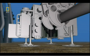
Dry welding is carried out in chamber sealed around the structure to be welded. The chamber is filled with a gas (commonly helium containing 0.5 bar of oxygen) at the prevailing pressure. The habitat is sealed onto the pipeline and filled with a breathable mixture of helium and oxygen, at or slightly above the ambient pressure at which the welding is to take place. This method produces high-quality weld joints that meet X- ray and code requirements. The gas tungsten arc welding process is employed for this process. The area under the floor of the Habitat is open to water. Thus the welding is done in the dry but at the hydrostatic pressure of the sea water surrounding the Habitat.

Untitled

Hyperbaric Chamber

(Source: National Geography Mega Structures episode Super Pipeline)

There is a risk to the welder/diver of electric shock. Precautions include achieving adequate electrical insulation of the welding equipment, shutting off the electricity supply immediately the arc is extinguished, and limiting the open-circuit voltage of MMA (SMA) welding sets. Secondly, hydrogen and oxygen are produced by the arc in wet welding.

Precautions must be taken to avoid the build-up of pockets of gas, which are potentially explosive. The other main area of risk is to the life or health of the welder/diver from nitrogen introduced into the blood steam during exposure to air at increased pressure. Precautions include the provision of an emergency air or gas supply, stand-by divers, and decompression chambers to avoid nitrogen narcosis following rapid surfacing after saturation diving.

For the structures being welded by wet underwater welding, inspection following welding may be more difficult than for welds deposited in air. Assuring the integrity of such underwater welds may be more difficult, and there is a risk that defects may remain undetected.

Advantages of Dry Welding

  1. Welder/Diver Safety – Welding is performed in a chamber, immune to ocean currents and marine animals. The warm, dry habitat is well illuminated and has its own environmental control system (ECS).
  2. Good Quality Welds – This method has ability to produce welds of quality comparable to open air welds because water is no longer present to quench the weld and H2 level is much lower than wet welds.
  3. Surface Monitoring – Joint preparation, pipe alignment, NDT inspection, etc. are monitored visually.
  4. Non-Destructive Testing (NDT) – NDT is also facilitated by the dry habitat environment.

Disadvantages of Dry Welding

  1. The habitat welding requires large quantities of complex equipment and much support equipment on the surface. The chamber is extremely complex.
  2. Cost of habitat welding is extremely high and increases with depth. Work depth has an effect on habitat welding. At greater depths, the arc constricts and corresponding higher voltages are required. The process is costly – a $ 80000 charge for a single weld job. One cannot use the same chamber for another job, if it is a different one.

Source:

Click to access underwater-welding.pdf

Riser Design: Riser Designing Procedure

Riser is defined as the vertical or near-vertical segment of pipe connecting the facilities above water to the subsea pipeline. The riser portion extends (as a minimum) from the first above- water valve or isolation flange to a point five pipe diameters beyond the bottom elbow, based on codes. The design engineer must select the exact limits on a case-by-case basis. This may often extend the riser beyond the five diameters limit or above the isolation flange. Many operators prefer a length of 200 feet from the elbow to protect against dropped objects (i.e., heavier wall pipe). The riser design usually considers adjoining pipework segments, clamps, supports, guides, and expansion absorbing devices.

sbs3f - Click for Next Image...

Riser Schematic (Source : Guo, Bouyun. Offshore Pipeline)

For a conventional steel riser, the design procedure includes the following steps:

Step 1: Establish the design basis.

  • Maximum wave height and period for return periods of 1 and 100 years
  •  Annual significant wave height occurrence in 5-foot height intervals
  •  Associated wave periods for annual significant wave height distribution
  •  Steady current profile
  •  Seismicity (if applicable)
  •  Splash zone limits
  •  Befouling thickness profile
  •  Minimum pipeline installation temperature
  •  Maximum allowable operating pressure (MAOP)
  •  Maximum allowable pipeline operating temperature (This should reflect the effects of temperature drop along pipeline in the direction of flow.)
  • Pipe-to-soil longitudinal friction
  • Soil elastic modulus

Step 2: Obtain platform design data.

  • Jacket design drawings
  • Batter of the jacket on the riser face
  • Movements of the platform during storm (100-year)
  • Intended riser locations: cellar deck plan

Step 3: Determine the minimum wall thickness for riser based on design pressure, pipe size, material grade, and corrosion allowance. This is defined by code formula and allowable hoop stress.

Step 4: Select a base riser configuration and perform static stress analyses for selected load cases. The detailed procedure is illustrated in the next section.

Step 5: Perform vortex shedding and fatigue analyses using cumulative damage methods to verify life of riser.

Step 6: Modify clamp locations, riser design, or wall thickness as necessary to meet codes and re-analyses for all cases.

Step 7: Design riser clamps based on jacket design and the forces calculated from static stress analysis.

Step 8: Design riser anchor at top clamp, if needed. This is generally only required in water depths greater than 100 feet where the riser cannot be free-standing.


Source :
Guo, Bouyun. Offshore Pipeline

Flexible Pipe: Introduction to Flexible Pipe

Flexible pipes have been used in the oil industry since 1972, when Coflexip was awarded a patent to build a high pressure, flexible steel pipe. The first application was used in drilling as a 15,000 psi Kill and Choke line. Since then, flexible pipe designs have improved to produce the flowlines and risers that are now used in the offshore oil industry.

For deepwater, the flexible pipes are used mainly for dynamic risers from a subsea pipeline end manifold (PLEM) or riser tower to a floating production system such as an FSO, FPSO, and TLPs. The other uses are static risers, static flowlines, subsea jumpers, topside jumpers, and expansion joints. Flexible pipes are used for versatile offshore oil and gas applications including production, gas lift, gas injection, water injection, and various ancillary lines including potable water and liquid chemical lines.

The main advantages of flexible pipelines are:

  •  Ease and speed of installation
  •  No large spans because it follows the contours of the seabed
  •  Almost no maintenance for life of the project
  •  Good insulation properties are inherent
  •  Excellent corrosion properties
  •  No field joints because the pipe is of continuous manufacture
  •  No need of expansion loops
  •  Can be made with enhanced flow characteristics
  •  Sufficient submerged weight for lateral stability
  •  Accommodates misalignments during installation and tie-in operations
  •  Diverless installation is possible—no metrology necessary
  •  Load-out and installation is safer, faster, and cheaper than any other pipe application
  •  Retrievability and reusability for alternative application, thus enhancing overall field development economics and preserving the environment
  •  Fatigue life longer than steel pipe

Source:

Guo, Bouyun. Offshore Pipeline

Offshore Pipeline Installation: S-Lay

The name S-lay refers to the shape the pipe assumes on its passage to the seabed. The pipe is assembled in a horizontal working plane, the firing line, by welding together sections of steel pipe. As welding progresses, the pipeline is gradually lowered to the seabed behind the ship, supported by a ‘stinger’, a steel structure protruding from the end of the firing line for support of the pipeline on rollers, to avoid pipe buckling. After a pipeline has been laid, the client oil company can transport oil or gas through it.

When performing S-lay pipeline installation, pipe is eased off the stern of the vessel as the boat moves forward. The pipe curves downward from the stern through the water until it reaches the “touchdown point,” or its final destination on the seafloor. As more pipe is welded in the line and eased off the boat, the pipe forms the shape of an “S” in the water.

S-Lay Pipeline Installation

S-Lay Pipeline Installation(Source: www.pbjv.com.my)

Stingers, measuring up to 300 feet (91 meters) long, extend from the stern to support the pipe as it is moved into the water, as well as control the curvature of the installation. Some pipelay barges have adjustable stingers, which can be shortened or lengthened according to the water depth. Proper tension is integral during the S-lay process, which is maintained via tensioning rollers and a controlled forward thrust, keeping the pipe from buckling. S-lay can be performed in waters up to 6,500 feet (1,981 meters) deep, and as many as 4 miles (6 kilometers) a day of pipe can be installed in this manner.

Source:

http://www.rigzone.com/training/insight.asp?insight_id=311&c_id=19

http://www.allseas.com/uk/33/company/activities/pipeline-installation.html
Pipeline Routing: Factors to Consider

When layout the field architecture, several considerations should be accounted for:

  • Compliance with regulation authorities and design codes
  • Future field development plan
  • Environment, marine activities, and installation method
  • Overall project cost
  • Seafloor topography
  • Interface with existing subsea structures


The pipeline route should be selected considering:

  • Low cost (select the most direct and shortest pipeline route)
  • Seabed topography (faults, outcrops, slopes, etc.)
  • Obstruction, debris, existing pipelines or structures
  • Environmentally sensitive areas (beach, oyster field, etc.)
  • Marine activity in the area such as fishing or shipping
  • Installability (1st end initiation and 2nd end termination)
  • Required pipeline route curvature radius
  • Riser hang-off location at surface structure
  • Riser corridor/clashing issues with existing risers
  • Tie-in methods

Source :

Lee, Jaeyoung. Introduction to Offshore Pipelines & Risers

Offshore Pipeline Corrosion Prevention: Cathodic Protection

Cathodic protection is an electro-chemical process where the ‘energy’ of the pipe steel surface is lowered to a point at which corrosion is no longer thermodynamically favorable. The electro-chemical reactions for cathodic protection are demonstrated by both the anodic and cathodic reactions respectively:

Fe –> Fe2+ + 2e-

2H+ + 2e- –> H2

In order to prevent the dissolution of elemental iron it must receive two electrons from a source, namely the cathodic protection unit. This in turn results in the formation of hydrogen gas at the surface of the steel commonly known as the passivation layer.

Typically there are two types of cathodic protection systems:

  • Impressed – This cathodic protection system works by applying a small current (typically milliamps per kilometre) to the pipeline via units known as transformer-rectifiers. These units convert AC electricity into DC and use this electricity to lower the ‘energy’ of the pipeline. This system enables an asset owner to protect several kilometres of pipeline, provided the AC power remains connected.
  • Sacrificial – This cathodic protection system essentially performs a similar function via the electrical connection made between the pipeline and the buried anodes, namely zinc or magnesium. This system differs in that the DC electricity generated is due to the galvanic difference between the pipeline and the anodes. This system is also limited in protection range but is relatively maintenance free, however the anodes have a finite life and will need to be replaced.

Main advantages of cathodic protection systems:

  • Low capital and operational cost per kilometer;
  • Protection against extensive range of environmental conditions;
  • Typically simple installation set-up; and,
  • Extremely effective at arresting the corrosion rate.

Source :

http://pipeliner.com.au/news/cathodic_protection_explained/063795/